This post came about after speaking to one of our Telco customers here in Europe. The customer is a long-term user of ScaleIO/VxFlexOS/PowerFlex and as well as having some large deployments, they also have several small edge deployments that they use for NFV type use cases. They are very experienced at deployments with of PowerFlex 3.x and below, but in their words, they found the details of deploying PowerFlex 4.x somewhat complex and the documentation to be somewhat disjointed.
This particular customer use case requires a very low footprint, hence an additional management server or cluster to host PowerFlex Manager virtual machines, is out of the question.
I pointed the customer towards the section of the Dell PowerFlex 4.5.x Install and Upgrade Guide that details the installation of the management stack as co-resident i.e. running on the storage nodes alongside the other PowerFlex software components. Whilst grateful for this information, they pointed out that there seems to be no option for a three node solution, everything depends on a fourth node or virtual machine to deploy the three node management stack, this node can be temporary and reused afterwards, but is required.
After re-reading the documentation, I came to the conclusion that the customer was absolutely correct (about the node requirement as well as the documentation), consequently I set myself the task of achieving a deployment on just three nodes. I did hit a number of roadblocks, later in this post I will explain how I overcame them.
Please note: Co-resident management is only supported for PowerFlex software only or custom node deployments. PowerFlex rack or appliance deployments, require a mandatory external management node or cluster running VMware to host the PowerFlex Manager virtual machines.
In addition, for the majority of uses cases, it is highly recommended to use a minimum of four storage nodes rather than the three deployed here in this edge case. The process used here could deploy many nodes, three nodes were used to prove it is possible.
According to the documentation, co-resident management is supported on the following platforms:
- Red Hat Enterprise Linux (RHEL) 7.9, 8.6 and 8.8
- SUSE Enterprise Linux (SLES) 15 SP3 and 15 SP4
- CentOS 7.9
I decided to go with RHEL 8.8
Note: I did also repeat the process with RHEL 9.2 and it worked absolutely fine, however at the time of writing, this has not been qualified.
The first step is to install Linux on the three nodes, my preference is to select a minimal deployment and then add packages as required. I installed using Virtual Media attached to the Out of Band iDRAC controller but any other method could be used.
Once the three nodes are deployed, the networks need to be configured. With RHEL 8 and above, I am actually starting to like nmcli as a tool to configure the networks which are managed by NetworkManager, perhaps I am just a glutton for punishment.
In the example below, I use the first port on each network card to create an active/standby bond to carry the management VLAN 105, I then trunk each PowerFlex data VLAN, 151 and 152, to a separate port. The network could be configured in other ways, for instance some like to use LACP , personally I find this simple approach to work best.
# nmcli con del ens2f0 ens2f1 ens3f0 ens3f1
# nmcli con add type bond con-name bond0 ifname bond0 ipv4.method disabled ipv6.method disabled
# nmcli con mod bond0 bond.options mode=1,miimon=100
# nmcli con mod bond0 802-3-ethernet.mtu 9000
# nmcli con add type bond-slave ifname ens2f0 con-name ens2f0 802-3-ethernet.mtu 9000 master bond0
# nmcli con add type bond-slave ifname ens3f0 con-name ens3f0 802-3-ethernet.mtu 9000 master bond0
# nmcli con add type vlan con-name bond0.105 ifname bond0.105 dev bond0 id 105 802-3-ethernet.mtu 1500 connection.autoconnect yes ip4 192.168.105.31/24 gw4 192.168.105.1
# nmcli con mod bond0.105 ipv4.dns "192.168.105.11,192.168.105.12" ipv4.dns-search dellpowerflex.com
# nmcli con up bond0
# nmcli con up bond0.105

# nmcli con add type ethernet con-name ens2f1 ifname ens2f1 ipv4.method disabled ipv6.method disabled 802-3-ethernet.mtu 9000 connection.autoconnect yes
# nmcli con add type ethernet con-name ens3f1 ifname ens3f1 ipv4.method disabled ipv6.method disabled 802-3-ethernet.mtu 9000 connection.autoconnect yes
# nmcli connection add type vlan con-name ens2f1.151 ifname ens2f1.151 dev ens2f1 id 151 ipv6.method ignore 802-3-ethernet.mtu 9000 connection.autoconnect yes ip4 192.168.151.31/24
# nmcli connection add type vlan con-name ens3f1.152 ifname ens3f1.152 dev ens3f1 id 152 ipv6.method ignore 802-3-ethernet.mtu 9000 connection.autoconnect yes ip4 192.168.152.31/24
# nmcli con up ens2f1
# nmcli con up ens3f1
# nmcli con up ens2f1.151
# nmcli con up ens3f1.152
If a valid Red Hat subscription is available and there is access to a subscription service, the nodes should be registered and attached to it.
If a subscription is unavailable or the installation is being done offline, an ISO image can be mounted through virtual media and be configured as a source for software installation
# mkdir /media/cdrom
# mount /dev/cdrom /media/cdrom

# cat >/etc/yum.repos.d/rhel8_8dvd.repo <<EOF
[Local-BaseOS]
name=Red Hat Enterprise Linux 8 - BaseOS
metadata_expire=-1
gpgcheck=1
enabled=1
baseurl=file:///media/cdrom/BaseOS/
gpgkey=file:///etc/pki/rpm-gpg/RPM-GPG-KEY-redhat-release

[Local-AppStream]
name=Red Hat Enterprise Linux 8 - AppStream
metadata_expire=-1
gpgcheck=1
enabled=1
baseurl=file:///media/cdrom/AppStream/
gpgkey=file:///etc/pki/rpm-gpg/RPM-GPG-KEY-redhat-release
EOF

# chmod 644 /etc/yum.repos.d/rhel8_8dvd.repo
# dnf clean all
# dnf repolist all
Updating Subscription Management repositories.
Unable to read consumer identity

This system is not registered with an entitlement server. You can use subscription-manager to register.

repo id                                 repo name                                                           status
Local-AppStream                         Red Hat Enterprise Linux 8 - AppStream                              enabled
Local-BaseOS                            Red Hat Enterprise Linux 8 - BaseOS                                 enabled
In order for the certificates used later in the process to work correctly and as a general good practice, each node should be configured to use a reliable time source. The default choice for RHEL 8 and above is chrony rather than ntp. Install it, edit the configuration file to define the time source(s), restart the service and then check that the sources are working.
# dnf install -y chrony
# vi /etc/chrony.conf
# systemctl restart chronyd
# chronyc sources
The first part of the process to deploy PowerFlex with a co-resident management stack is to manually deploy/configure the PowerFlex storage cluster.
There is a series of prerequisite packages listed in the PowerFlex documentation, I chose to install them all in one command.
# dnf install -y numactl libaio wget apr python3 python3-rpm python3-cryptography yum-utils bash-completion binutils java-11-openjdk-headless smartmontools binutils sg3_utils hdparm pciutils ndctl jq daxio libpmem
Run the following pip command
# pip3 install --upgrade pip
To install the PowerFlex software packages they should be downloaded from the Dell support site and then copied to a directory on each of the three storage nodes. I copied them under the home directory of the delladmin user (that I configured at deployment time). You can see that version 4.5.1 of PowerFlex was used here.
Firstly install activemq, the LIA and SDS on to all three nodes
Note: the activemq service may not run at this point, after installing PowerFlex Manager, it needs to be restarted.
# rpm -ivh /home/delladmin/PowerFlex_4.5.1000.103_RHEL_OEL8/EMC-ScaleIO-activemq-5.18.3-66.noarch.rpm
# TOKEN=Scaleio123 rpm -ivh /home/delladmin/PowerFlex_4.5.1000.103_RHEL_OEL8/EMC-ScaleIO-lia-4.5-1000.103.el8.x86_64.rpm
# rpm -ivh /home/delladmin/PowerFlex_4.5.1000.103_RHEL_OEL8/EMC-ScaleIO-sds-4.5-1000.103.el8.x86_64.rpm
Next the MDM component is deployed on each of the three nodes.
The MDM cluster will consist of a primary, secondary and tiebreaker node.
On the primary and secondary nodes
# MDM_ROLE_IS_MANAGER=1 rpm -ivh /home/delladmin/PowerFlex_4.5.1000.103_RHEL_OEL8/EMC-ScaleIO-mdm-4.5-1000.103.el8.x86_64.rpm
On the tiebreaker node
# MDM_ROLE_IS_MANAGER=0 rpm -ivh /home/delladmin/PowerFlex_4.5.1000.103_RHEL_OEL8/EMC-ScaleIO-mdm-4.5-1000.103.el8.x86_64.rpm
In PowerFlex 4.x, a new certificate based trust system was introduced that will only allow the MDM services to communicate if the necessary certificates are in place. It is therefore a requirement to generate the certificates and copy them to the correct location.
From the primary MDM node run these commands to generate the certificates
# cd /opt/emc/scaleio/mdm/cfg
# python3 certificate_generator_MDM_USER.py --generate_ca mgmt_ca.pem --password Scaleio123
# python3 certificate_generator_MDM_USER.py --generate_cli cli_certificate.p12 -CA mgmt_ca.pem --password Scaleio123
# python3 certificate_generator_MDM_USER.py --generate_mdm mdm_certificate.pem -CA mgmt_ca.pem
# python3 certificate_generator_MDM_USER.py --generate_mdm sec_mdm_certificate.pem -CA mgmt_ca.pem
Copy the generated certificates to the secondary MDM node
# scp sec_mdm_certificate.pem root@<Secondary IP Address>:/opt/emc/scaleio/mdm/cfg/mdm_certificate.pem
# scp cli_certificate.p12 root@<Secondary IP Address>:/opt/emc/scaleio/mdm/cfg/
# scp mgmt_ca.pem root@<Secondary IP Address>:/opt/emc/scaleio/mdm/cfg/
On both the primary and secondary MDM nodes add the certificate
# cd /opt/emc/scaleio/mdm/cfg; scli --add_certificate --certificate_file mgmt_ca.pem ; cd $HOME
On all three nodes, restart the MDM service
# systemctl restart mdm.service
To create the three node MDM cluster, firstly a single node cluster is created.
Login to this cluster using the password provided in the certificate configuration section above
NOTE: Make a copy of the System ID that is shown on login, you will need this later!! (in bold below)
The other MDM roles are added to it, then it is switched to a three node cluster.
Use the scli –query_cluster command to check the status.
# scli --create_mdm_cluster --primary_mdm_ip 192.168.151.31,192.168.152.31 --primary_mdm_management_ip 192.168.105.31 --primary_mdm_name MDM31 --cluster_virtual_ip 192.168.151.30,192.168.152.30 --primary_mdm_virtual_ip_interface ens2f1.1057,ens3f1.1058 --approve_certificate

# scli --login --p12_path /opt/emc/scaleio/mdm/cfg/cli_certificate.p12
Enter p12 password:
Logged in. User role is SuperUser. System ID is 769cd0d527e2510f

# scli --add_standby_mdm --new_mdm_ip 192.168.151.32,192.168.152.32 --mdm_role manager --new_mdm_management_ip 192.168.105.32 --new_mdm_virtual_ip_interface ens2f1.1057,ens3f1.1058 --new_mdm_name MDM32

# scli --add_standby_mdm --new_mdm_ip 192.168.151.33,192.168.152.33 --mdm_role tb --new_mdm_name MDM33

# scli --switch_cluster_mode --cluster_mode 3_node --add_secondary_mdm_name MDM32 --add_tb_name MDM33

# scli --query_cluster
Cluster:
    Mode: 3_node, State: Normal, Active: 3/3, Replicas: 2/2
    SDC refresh with MDM IP addresses: disabled
    Virtual IP Addresses: 192.168.151.30, 192.168.152.30
Primary MDM:
    Name: MDM31, ID: 0x1ebc56c862f41d00
        IP Addresses: 192.168.151.31, 192.168.152.31, Port: 9011, Virtual IP interfaces: ens2f1.1057, ens3f1.1058
        Management IP Addresses: 192.168.105.31, Port: 8611
        Status: Normal, Version: 4.5.1000
Secondary MDMs:
    Name: MDM32, ID: 0x572db6944cc81001
        IP Addresses: 192.168.151.32, 192.168.152.32, Port: 9011, Virtual IP interfaces: ens2f1.1057, ens3f1.1058
        Management IP Addresses: 192.168.105.32, Port: 8611
        Status: Normal, Version: 4.5.1000
Tie-Breakers:
    Name: MDM33, ID: 0x35417ee7401a8602
        IP Addresses: 192.168.151.33, 192.168.152.33, Port: 9011
        Status: Normal, Version: 4.5.1000
Now that we have an MDM cluster running, we can create the PowerFlex data constructs. In this example, we will have a single Protection Domain, containing a single Storage Pool, three SDS nodes each with ten attached disks, in the one Storage Pool – this is really as simple as it can be.
The final command defines the percentage of spare capacity that should be defined in the Storage Pool. It will default to 10% as it assumes you will be using ten or more nodes. For our very small environment with only three nodes, we need to ensure that at least a third is reserved in order to protect against the failure of an entire node, you will be asked to confirm this spare capacity by entering y.
# scli --add_protection_domain --protection_domain_name PD1

# scli --add_storage_pool --protection_domain_name PD1 --dont_use_rmcache --media_type SSD --data_layout medium_granularity --storage_pool_name PD1_SP1

# scli --add_sds --sds_ip 192.168.151.31,192.168.152.31 --protection_domain_name PD1 --storage_pool_name PD1_SP1 --disable_rmcache --sds_name PFMC-SDS-31

# scli --add_sds --sds_ip 192.168.151.32,192.168.152.32 --protection_domain_name PD1 --storage_pool_name PD1_SP1 --disable_rmcache --sds_name PFMC-SDS-32

# scli --add_sds --sds_ip 192.168.151.33,192.168.152.33 --protection_domain_name PD1 --storage_pool_name PD1_SP1 --disable_rmcache --sds_name PFMC-SDS-33

# scli --modify_spare_policy --protection_domain_name PD1 --storage_pool_name PD1_SP1 --spare_percentage 34
To add the individual disks on each node to the Storage Pool, it is possible to do them one by one, however I am lazy and will use bash to help me out whenever I can, if it reduces the amount of typing required. Before running these commands, check how the nodes have ordered the drives. My boot disk is /dev/sda but this is not always the case and sometimes it can even differ across nodes.
# for i in {b..k}; do scli --add_sds_device --sds_name PFMC-SDS-31 --storage_pool_name PD1_SP1 --device_path /dev/sd${i} --force_device_takeover; done
# for i in {b..k}; do scli --add_sds_device --sds_name PFMC-SDS-32 --storage_pool_name PD1_SP1 --device_path /dev/sd${i} --force_device_takeover; done
# for i in {b..k}; do scli --add_sds_device --sds_name PFMC-SDS-33 --storage_pool_name PD1_SP1 --device_path /dev/sd${i} --force_device_takeover; done
The whole purpose of a co-resident PowerFlex deployment is that the PowerFlex Manager software runs on the same nodes as the PowerFlex software. The PowerFlex Manager software requires disk capacity to run, currently we do not support this on the BOSS boot device but instead present storage from the PowerFlex storage, to the nodes. In order to present storage to the nodes, they require the PowerFlex SDC component to be installed, the SDC also has a few dependencies which are installed first.
# dnf install -y tar unzip zstd
# MDM_IP=192.168.151.30,192.168.152.30 rpm -ivh /home/delladmin/PowerFlex_4.5.1000.103_RHEL_OEL8/EMC-ScaleIO-sdc-4.5-1000.103.el8.x86_64.rpm
Occasionally, there can be issues with selinux preventing the SDC from running properly (the scini driver does not load), in order to get around this, either set selinux to permissive or disabled, alternatively follow the process below
# cat >/tmp/scini.fe <<EOF1
/usr/bin/emc/scaleio/(.*).ko system_u:object_r:modules_object_t:s0
/bin/emc/scaleio/(.*).ko system_u:object_r:modules_object_t:s0
EOF1

cat >/tmp/scini.te <<EOF2
module scini 1.0;
require {
type insmod_t;
type modules_object_t;
class system module_load;
}
EOF2

checkmodule -M -m /tmp/scini.te -o /tmp/scini.mod
semodule_package -o /tmp/scini.pp -m /tmp/scini.mod -f /tmp/scini.fe
semodule -i /tmp/scini.pp
restorecon -R -v /bin/emc/scaleio/

systemctl restart scini
Now is probably a good time to run a couple of scli commands from the primary MDM to confirm everything is configured as expected. Note: it may be necessary to login again.
# scli --login --p12_path /opt/emc/scaleio/mdm/cfg/cli_certificate.p12

# scli --query_all_sds
Query-all-SDS returned 3 SDS nodes.

Protection Domain e47b61a300000000 Name: PD1
SDS ID: 1095f27300000002 Name: PFMC-SDS-33 State: Connected, Joined IP: 192.168.151.33,192.168.152.33 Port: 7072 Version: 4.5.1000
SDS ID: 1095f27200000001 Name: PFMC-SDS-32 State: Connected, Joined IP: 192.168.151.32,192.168.152.32 Port: 7072 Version: 4.5.1000
SDS ID: 1095f27100000000 Name: PFMC-SDS-31 State: Connected, Joined IP: 192.168.151.31,192.168.152.31 Port: 7072 Version: 4.5.1000

# scli --query_all_sdc
MDM restricted SDC mode: NONE
SDC refresh with MDM IP addresses: disabled
3 SDCs have non-current MDM IP addresses. 3 SDCs have non-hardened MDM IP addresses.
Query all SDCs returned 3 SDCs.
SDC ID: afac345d00000000 Name: N/A IPs: 192.168.151.31,192.168.152.31 State: Connected GUID: F971B0FC-295F-4A71-A4CD-5284D52B6B81  OS Type: LINUX Loaded Version: 4.5.1000 Installed Version: 4.5.1000
    Agent status: disabled MDM IP addresses: stale Reboot safe: no
    Reads:  0 IOPS 0 Bytes per second
    Writes: 0 IOPS 0 Bytes per second
SDC ID: afac345e00000001 Name: N/A IPs: 192.168.151.32,192.168.152.32 State: Connected GUID: F2E23551-C455-4CAC-A3E1-D10ACED9A259  OS Type: LINUX Loaded Version: 4.5.1000 Installed Version: 4.5.1000
    Agent status: disabled MDM IP addresses: stale Reboot safe: no
    Reads:  0 IOPS 0 Bytes per second
    Writes: 0 IOPS 0 Bytes per second
SDC ID: afac345f00000002 Name: N/A IPs: 192.168.151.33,192.168.152.33 State: Connected GUID: 13871D80-D2CE-4C17-AE92-E833D76D1C95  OS Type: LINUX Loaded Version: 4.5.1000 Installed Version: 4.5.1000
    Agent status: disabled MDM IP addresses: stale Reboot safe: no
    Reads:  0 IOPS 0 Bytes per second
    Writes: 0 IOPS 0 Bytes per second
This next block of commands creates the volumes that PowerFlex Manager will use and maps them to the hosts (one to each).
One thing to highlight, I have used the ‘–volume_class management’ flag on each volume. The volume_class flags on a volume can be used to hide volumes from general users and make them more difficult to delete, for example these volumes will not appear in the PowerFlex web management interface, even at the command line, deleting them requires the –volume_class parameter to be defined.
(I am quite surprised that this option is not recommended in the official deployment guide).
# scli --add_volume --size_gb 600 --volume_name PFMC1_VOL --protection_domain_name PD1 --storage_pool_name PD1_SP1 --volume_class management
# scli --add_volume --size_gb 600 --volume_name PFMC2_VOL --protection_domain_name PD1 --storage_pool_name PD1_SP1 --volume_class management
# scli --add_volume --size_gb 600 --volume_name PFMC3_VOL --protection_domain_name PD1 --storage_pool_name PD1_SP1 --volume_class management
# scli --map_volume_to_sdc --volume_name PFMC1_VOL --volume_class management --sdc_ip 192.168.151.31
# scli --map_volume_to_sdc --volume_name PFMC2_VOL --volume_class management --sdc_ip 192.168.151.32
# scli --map_volume_to_sdc --volume_name PFMC3_VOL --volume_class management --sdc_ip 192.168.151.33
On each node, partition the newly presented PowerFlex volume and add an XFS filesystem on each partition. The deployment guide suggests doing this manually with fdisk however parted offers a very nice way of doing this through the command line.
# parted /dev/scinia mklabel gpt
# parted /dev/scinia mkpart primary 0.00GB 350.00GB
# parted /dev/scinia mkpart primary 350.00GB 450.00GB
# parted /dev/scinia mkpart primary 450.00GB 600.00GB

# mkfs.xfs /dev/scinia1
# mkfs.xfs /dev/scinia2
# mkfs.xfs /dev/scinia3
Next create the directories that these filesystems will be mounted to
# mkdir -p /opt/platform-provisioner
# mkdir -p /opt/platform
# mkdir -p /var/lib/rancher
The deployment guide suggests another a very manual method to mount the new filesystems and then add them to /etc/fstab, as mentioned earlier, I am lazy and if I can simplify something using bash or text manipulation, I will, hence this is my method
# echo "`ls -ld /dev/disk/by-id/* | grep scini | grep part1 | awk '{print $9}'` /opt/platform-provisioner  xfs  _netdev,x-systemd.requires=scini.service 0 0" >> /etc/fstab

# echo "`ls -ld /dev/disk/by-id/* | grep scini | grep part2 | awk '{print $9}'` /opt/platform              xfs  _netdev,x-systemd.requires=scini.service 0 0" >> /etc/fstab

# echo "`ls -ld /dev/disk/by-id/* | grep scini | grep part3 | awk '{print $9}'` /var/lib/rancher           xfs  _netdev,x-systemd.requires=scini.service 0 0" >> /etc/fstab

# mount -a
We now have storage presented to each node ready for the installation of the PowerFlex Manager platform. There are some additional software packages that need to be installed on each node prior to the deployment and they should be installed now.
# dnf install -y httpd-tools libselinux-python3 sshpass haproxy keepalived lvm2 skopeo firewalld iptables nmap
Up to this point, I have been following the deployment guide pretty much to the letter, hopefully adding some clarity, however this is the point where I start to deviate in order to be able to deploy on just three nodes. The standard process from this point, would be to introduce a fourth node or virtual machine, dedicated to running the installer container, which is used to provision the three node Kubernetes based PowerFlex Manager cluster. My goal was to run the container on one of the nodes whilst it deploys Kubernetes plus the PowerFlex Manager software components on to all three nodes, including the one it is running on.
As I work through the following steps, I will point out the modifications that were needed in order to make the process work.
Firstly, download the PowerFlex Manager bundle from the Dell support site, which is supplied as a tgz file. For this document, I used version 4.5.1.1 – PFMP2-4.5.1.1-4.tgz
I copied the file under /opt/dell/pfmp and extracted it there (I also changed the ownership to root:root as the tar has been created with some obscure ownership).
# mkdir -p /opt/dell/pfmp
# cd /opt/dell/pfmp
# tar zxf PFMP2-4.5.1.1-4.tgz
# chown -R root:root /opt/dell/pfmp
The file that defines how the PowerFlex Manager Kubernetes cluster is deployed is PFMP_Config.json, it must be edited very carefully according to the environment.
The top section defines the nodes that will be used for the cluster.
The two reserved pools of IP addresses are used privately by the Kubernetes cluster and in general, there is no need to modify these.
The routable CIDR networks are important, these can be an entire CIDR or a defined range of IP addresses. They must be currently unused as they will be allocated to services running in the cluster that require external IP addresses.
The OOB range is only required for PowerFlex rack or appliance deployments where the management stack communicates with the nodes over their iDRAC Out of Band managment.
The PFMPHostName must be resolvable to the PFMPHostIP and this IP address should be the first in the mgmt range of addresses.
# vi /opt/dell/pfmp/PFMP_Installer/config/PFMP_Config.json
{
  "Nodes": [
    {
      "hostname": "sds31",
      "ipaddress": "192.168.105.31"
    },
    {
      "hostname": "sds32",
      "ipaddress": "192.168.105.32"
    },
    {
      "hostname": "sds33",
      "ipaddress": "192.168.105.33"
    }
  ],
  "ClusterReservedIPPoolCIDR": "10.42.0.0/23",
  "ServiceReservedIPPoolCIDR": "10.43.0.0/23",
  "RoutableIPPoolCIDR": [
    {
      "mgmt": "192.168.105.55 - 192.168.105.59"
    },
    {
      "data1": "192.168.151.55 - 192.168.151.59"
    },
    {
      "data2": "192.168.152.55 - 192.168.152.59"
    }
  ],
  "PFMPHostname": "corespfmgr.dellpowerflex.com",
  "PFMPHostIP": "192.168.105.55"
}
All the scripts to perform the installation are in the /opt/dell/pfmp/PFMP_Installer/scripts directory with the two key ones being setup_installer.sh and install_PFMP.sh
The setup_installer.sh script, uses docker to extract an image from a tar file and then run this image as a container. Red Hat made the decision from RHEL 8 onwards to not use docker but instead to use podman. The good news is that there is a package called podman-docker which takes any docker command and converts it to a podman command. Each docker command will issue a warning but these can be suppressed by creating the /etc/containers/nodocker file.
# dnf install -y podman podman-docker
# touch /etc/containers/nodocker
It was at this point that I hit the two roadblocks I mentioned at the start which initially slowed my progress.
The first was that there is a clash between the network plugin used by the container used to create the cluster and the network plugin that the Kubernetes cluster uses. The container runs fine, creating a network called pfmp_installer_nw, that bad news is that when the Kubernetes cluster deploys, it somehow tries to grab this network and falls over in a heap. The good news is that with podman version 4, there is a new network option called netavark (https://www.redhat.com/sysadmin/podman-new-network-stack) which eliminates this ‘clash’. It is necessary to install it and then set it as the default network_backend for podman (interestingly, with RHEL 9.2, netavark was installed automatically with podman).
# dnf install -y netavark

# mkdir -p /etc/containers/containers.conf.d
# echo "[network]" > /etc/containers/containers.conf.d/pfmp.conf
# echo 'network_backend = "netavark"' >> /etc/containers/containers.conf.d/pfmp.conf
The second issue I hit was around how podman (and docker I believe) handle resets caused by firewalld. During the deployment of the PowerFlex Manager Kubernetes cluster, a number of firewall ports are opened and firewall resets performed. This has a catastrophic effect on podman networks as discussed here https://github.com/containers/podman/issues/5431 the podman developers became aware of this and added a ‘podman network reload –all’ option in order to restore the podman network. This is great, however it requires manual intervention and with our deployment script performing the deployment automatically, it would require monitoring and someone to manually enter the command when the deployment stops. Now the really good news, is that someone really clever on that same github page has come up with a method to monitor the system in order to detect firewall resets and automatically run the ‘podman network reload –all’ command https://github.com/containers/podman/issues/5431#issuecomment-1022121559
# vi /etc/systemd/system/podman-firewalld-reload.service

# /etc/systemd/system/podman-firewalld-reload.service
[Unit]
Description=Redo podman NAT rules after firewalld starts or reloads
Wants=dbus.service
After=dbus.service

[Service]
Type=simple
Environment=LC_CTYPE=C.utf8
ExecStart=/bin/bash -c "dbus-monitor --profile --system 'type=signal,sender=org.freedesktop.DBus,path=/org/freedesktop/DBus,interface=org.freedesktop.DBus,member=NameAcquired,arg0=org.fedoraproject.FirewallD1' 'type=signal,path=/org/fedoraproject/FirewallD1,interface=org.fedoraproject.FirewallD1,member=Reloaded' | sed -u '/^#/d' | while read -r type timestamp serial sender destination path interface member _junk; do if [[ $type = '#'* ]]; then continue; elif [[ $interface = org.freedesktop.DBus && $member = NameAcquired ]]; then echo 'firewalld started'; podman network reload --all; elif [[ $interface = org.fedoraproject.FirewallD1 && $member = Reloaded ]]; then echo 'firewalld reloaded'; podman network reload --all; fi; done"
Restart=always

[Install]
WantedBy=multi-user.target


# systemctl daemon-reload
# systemctl enable --now podman-firewalld-reload.service
So now I have all protection in place that allows me to run the PowerFlex Manager deployment scripts.
As stated above, the setup_installer.sh script will deploy the container that performs the actual deployment. You can check that the netavark backend is being used by checking that the network is defined in /etc/containers/networks rather than /etc/cni/net.d
# cd /opt/dell/pfmp/PFMP_Installer/scripts
# ./setup_installer.sh

# ls /etc/containers/networks/
pfmp_installer_nw.json
# ls /etc/cni/net.d/
The second installation script install_PFMP.sh can now be run. There are a few questions to answer at the start. This is a good point to stop for lunch, have a lengthy drinks break or whatever you like to kill the hour or so this script takes to run…
# ./install_PFMP.sh
RUN_PARALLEL_DEPLOYMENTS is not set.
RUN_PARALLEL_DEPLOYMENTS is set to: false

Running Single Deployment flow mode

ATL_BASE_URL_ENV http://atlantic_installer:8383
/usr/lib/python3.10/site-packages/paramiko/transport.py:236: CryptographyDeprecationWarning: Blowfish has been deprecated
  "class": algorithms.Blowfish,
2024-01-17 18:54:53,030 | INFO | Setting up cluster deployment to on-prem
Installation logs are available at <Bundle root>/PFMP_Installer/logs/ directory.
More detailed logs are available at <Bundle root>/atlantic/logs/ directory.
PFMP Installer is about to deploy a PFMP cluster based on the configuration specified in the PFMP_Config.json.
Are ssh keys used for authentication connecting to the cluster nodes[Y]?:n
Please enter the ssh username for the nodes specified in the PFMP_Config.json[root]:
Are passwords the same for all the cluster nodes[Y]?:
Please enter the ssh password for the nodes specified in the PFMP_Config.json.
Password:
Are the nodes used for the PFMP cluster, co-res nodes [Y]?:
2024-01-18 21:25:57,952 | INFO | Building cni network configuration for on-prem deployment type
2024-01-18 21:25:57,952 | INFO | Building cni network configuration for on-prem deployment type is succeeded
2024-01-18 21:25:57,952 | INFO | Building cloud provider configuration for on-prem deployment type
2024-01-18 21:25:57,952 | INFO | Building cloud provider configuration for on-prem deployment type is succeeded
2024-01-18 21:25:57,952 | INFO | Getting data from the config file.
2024-01-18 21:25:57,957 | INFO | Loading pfmp apps configuration file
2024-01-18 21:25:57,959 | INFO | Loading pfmp apps configuration file is succeeded
2024-01-18 21:25:57,959 | INFO | Setting up the cluster
100%|##################################################################################################################|
2024-01-18 21:42:35,574 | INFO | Deploying the apps
100%|##################################################################################################################|
2024-01-18 22:36:35,952 | INFO | Trying to connect to node:192.168.105.31
2024-01-18 22:36:36,739 | INFO | UI can be accessed at:corespfmgr.dellpowerflex.com which needs to be resolved to 192.168.105.55
2024-01-18 22:36:36,739 | INFO | Deployed the cluster and applications.
If the process completes successfully, you will see the line instructing you to point a browser at the PFMPHostname you entered into PFMP_Config.json and that this must resolve to the PFMPHostIP entered in the same file.
BUT before we jump in and start using the web GUI, there are a few very important items of housekeeping required to ensure everything continues to run after node reboots etc.
Because the PowerFlex Manager platform is running on top of an rke2 Kubernetes based platform and this relies on storage provided by PowerFlex, we must ensure that the Kubernetes service does not start unless the PowerFlex volumes have been mounted, in a similar way to the entries in /etc/fstab not allowing the mounts until the scini service (SDC) has started. This is achieved by editing the rke2-server systemd configuration on each node and adding the two lines in bold.
# systemctl edit --full rke2-server

[Unit]
Description=Rancher Kubernetes Engine v2 (server)
Documentation=https://github.com/rancher/rke2#readme
Wants=network-online.target
After=network-online.target
Conflicts=rke2-agent.service
RequiresMountsFor=/var/lib/rancher /opt/platform /opt/platform-provisioner
ConditionPathIsReadWrite=/var/lib/rancher /opt/platform /opt/platform-provisioner
Additionally and rather annoyingly, considering the effort to allow the deployment to complete with firewalld running, it is highly recommended to disable firewalld as it can conflict with the calico networking that rke2 utilises. Unfortunately, it cannot be disabled at the very start as the deployment process requires it – don’t shoot the messenger, I don’t make up the rules!!
For anyone concerned about this disabling of the firewall, the PowerFlex Manager team made some changes in version 4.5.1 that manages the open ports via a Global Network Policy in Kubernetes and uses iptables – https://www.dell.com/support/kbdoc/en-us/000217927
On each node
# systemctl disable --now firewalld
If you remember, we also created the podman-firewalld-reload service to allow the deployment to succeed. We should also disable that now, since it is no longer required, this only needs to be performed on the node that PowerFlex Manager was deployed from.
# systemctl disable --now podman-firewalld-reload.service
Finally, on the primary and secondary MDM, restart activemq to ensure that it communicates to PowerFlex Manager correctly and add the certificate – if this is not done, SCLI commands will not work.
# systemctl restart activemq.service
# scli --add_certificate --certificate_file /opt/emc/scaleio/mdm/cfg/mgmt_ca.pem
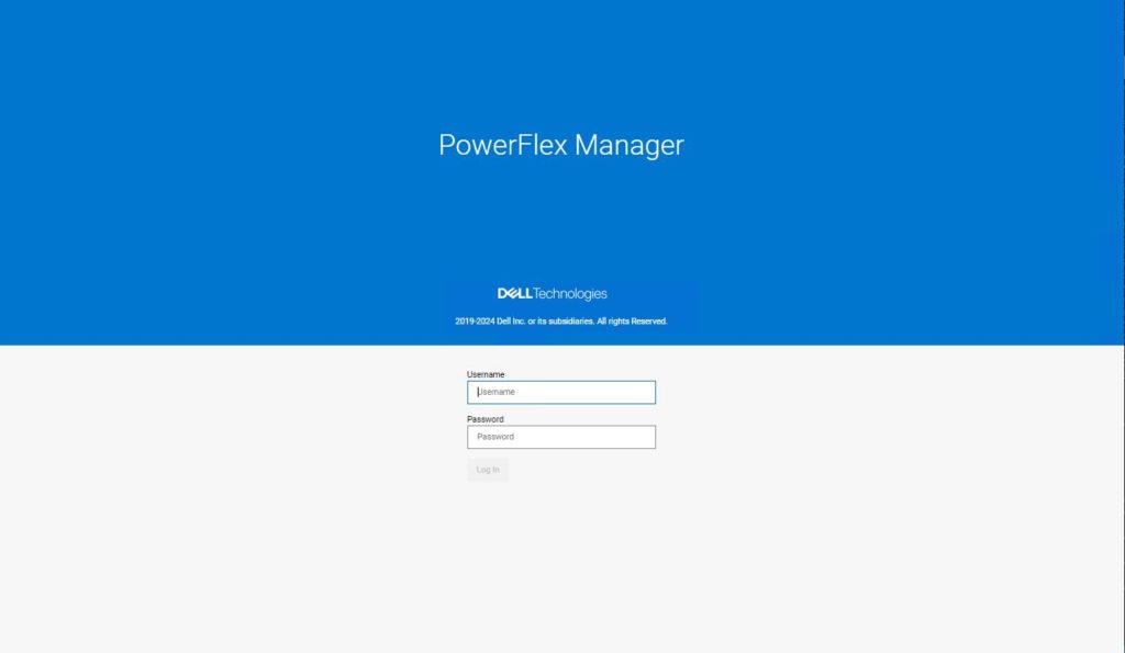
Finally, we can point our web browser at the hostname of PowerFlex Manager.
The following screen should appear in your browser window if you follow the instructions.
The initial username is admin with a password of Admin123!
You will be forced to change this on first login.
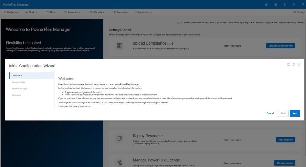
Once logged in, the Initial Configuration Wizard is presented. You now need to work through the process of adding the PowerFlex cluster that was created manually, into the PowerFlex Manager environment.
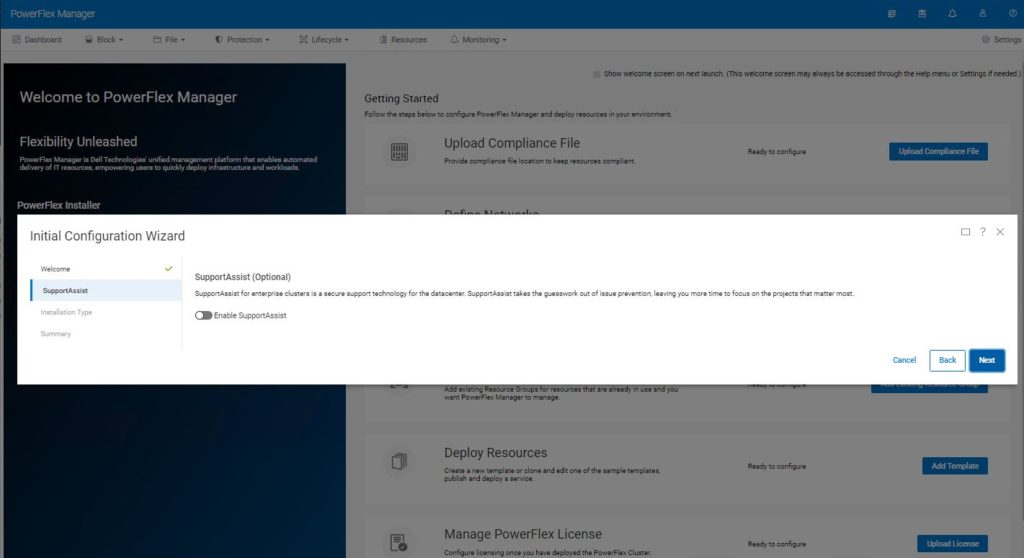
If you have an existing SupportAssist environment, PowerFlex Manager can be added to it, otherwise this step can be skipped by clicking next.
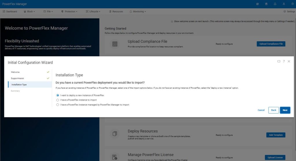
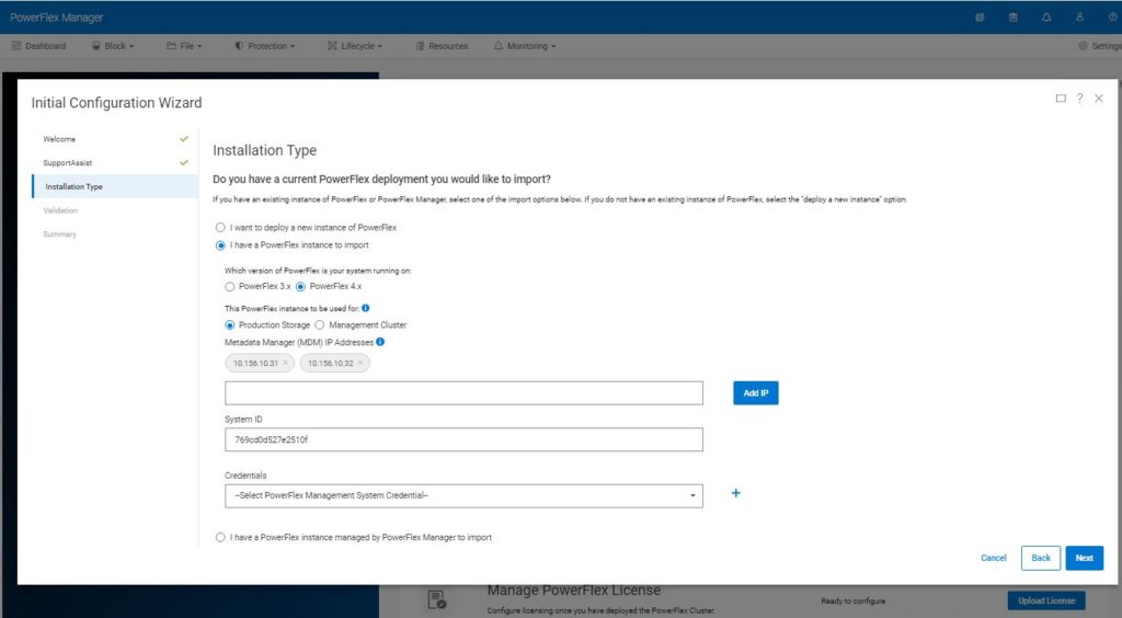
You are asked what kind of installation you want to perform. In this case, we want to import our manually created environment, so choose the second option ‘I have a PowerFlex instance to import’.
PowerFlex Manager now asks for some information about the system it should import.
Select the version of PowerFlex, here we have deployed PowerFlex 4.x
Select Production Storage, the Management Cluster option is specifically for PowerFlex rack deployments.
Enter the MANAGEMENT IP addresses of the MDM nodes (the observant will notice these are different from the deployment above).
Enter the System ID. If you were paying attention, you would have noticed that I suggested earlier in this procedure, that you should save this somewhere safe.
PowerFlex Manager needs the credentials of the LIA, this is what the ‘TOKEN=’ was set to when the LIA was deployed. Use the blue + sign to the right of the credentials box to create these new credentials in PowerFlex Manager.
Click next.
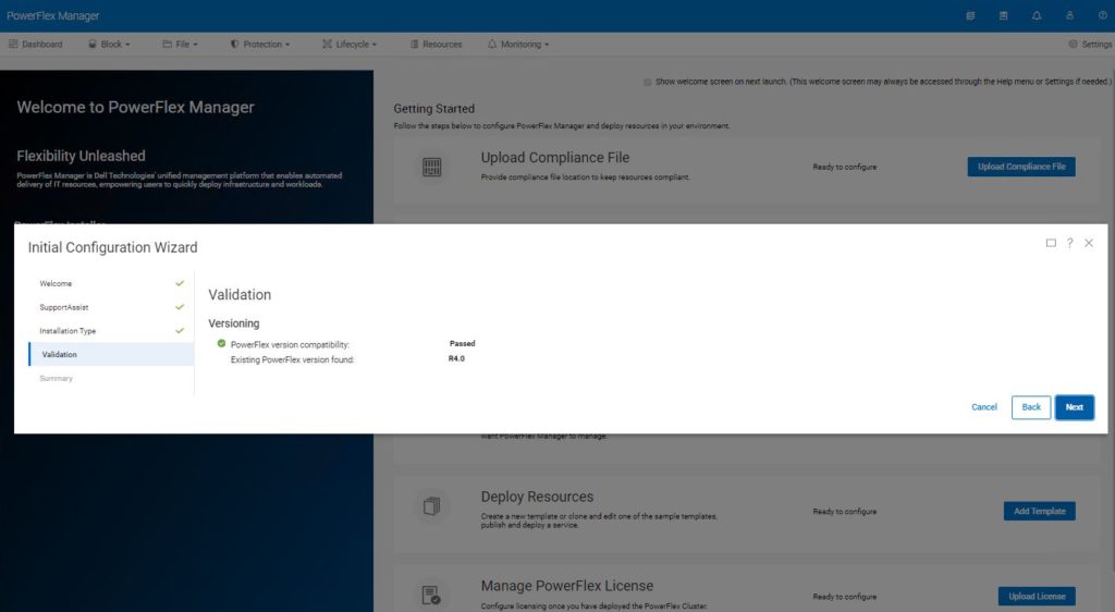
Provided all supplied information is correct, PowerFlex Manager will discover the existing PowerFlex cluster and verify its compatibility. Press next to continue.
After a few minutes, the screen should return to the Getting Started page. During the discover and configuration phase, activity would be reported by a green icon on the activity icon ringed below.

The process is now pretty much complete. It is a good idea to explore the PowerFlex Manager GUI. The dashboard is fairly self-explanatory.
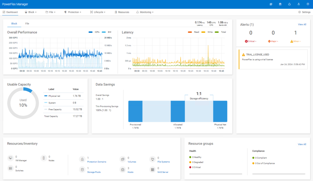
If you are familiar with earlier versions of PowerFlex/VxFlexOS/ScaleIO, the Block tab is likely to be where you will spend most of your time.
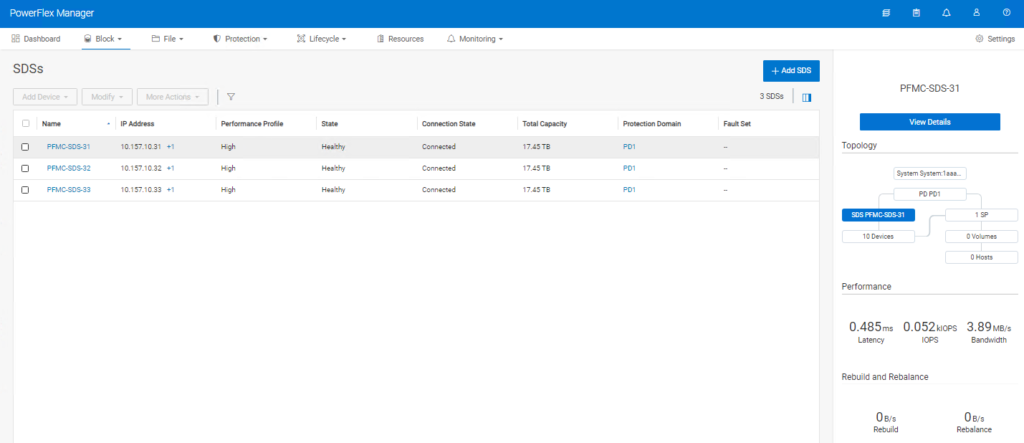
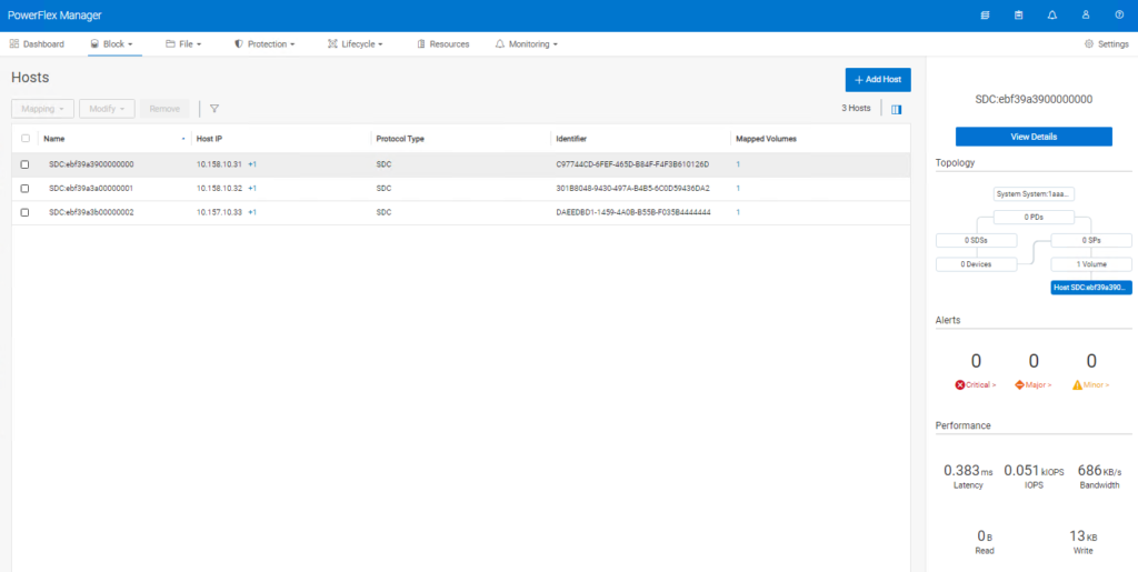
If you remember I set the ‘–volume_class management’ when creating the volumes to be used for management, in order to ‘hide’ them – look, no volumes!!

For those users who are familiar with using scli commands on older versions of PowerFlex, it is important to note that there is a new way to login, the user must be authenticated against the management stack.
# scli --login --username admin --management_system_ip 192.168.105.55
I realise that this article is relevant to a small number of PowerFlex users around the globe but I really hope those that read it, find it useful and that it clarifies certain parts of the documentation that is not 100% clear.
Many thanks for reading.
Kevin Jones
#Iwork4Dell
** Please do NOT reproduce without permission of the author **

Q. How do you get a person to Mars?
A. Tell Kevin Jones it can’t be done!
Quite possibly your finest work so far; this addresses a major bugbear that many users and salespeople have had alike!
It does appear to me that a non-containerised management stack option would have been a heck of a lot easier, but hopefully one day we’ll see all the advantages of the promised-land of containerised goodness.
Thank you so much both, Kevin & Matt…
Yes, it puzzle us (to help those custom-node users) to setup/demo the new 4.x environment…
So many detailed (container-command) steps are not included in the manual…. *sadly*
You show us some light in the dark….
Ryan
Many thanks for the very positive feedback.
Kevin Jones
hi! Kevin,
Hope you remember who I am… ^o^
&
Hope Matt&you are all well…
(sorry for the duplicate reply)
Ryan.