By Simon Stevens, Dell PowerFlex Engineering Technologist, July 2023.
Part of my day-to-day role is to help people learn about the product that I have lived and breathed for the past 10 years – PowerFlex. “Enabling customers to do better” is the name of the game and I have been lucky enough to have had lots of chances to do this over the past month – whether that has been by assisting some of our UK-based partners as they complete their “Fit2Flex” enablement training, creating content for internal consumption or helping out with the creation of solutions and white papers, the pace never slows down when you are helping to increase the reach & improve the understanding of a product that is front and centre of the Dell “Multicloud By Design” approach to the transformation of today’s technology infrastructure landscape.
Having said that, it pays to never assume that people understand all of the capabilities of a feature-rich product such as PowerFlex, even when they have been part and parcel of the product for a long time. One of the most talked-about features of PowerFlex are Fault Sets, yet they are also one of its most mis-understood subjects! My colleague Kevin Jones gave a great overview of what they are and how they work in a recent blog of his, that you can access here. However, what I will discuss in more detail in this blog are the implications of using Fault Sets when a node fails & rebuilds happen, as this appears to be one of those areas that frequently gets misunderstood. So, sit down dear reader and read on while I try to demystify this topic below!
The Basics of the PowerFlex Node Rebuild Process
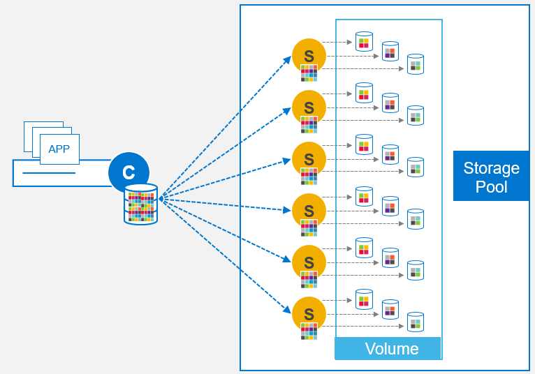
The PowerFlex distributed mesh-mirror architecture is one subject that is very well understood by most people who have used PowerFlex. Indeed, there is a ton of documentation, slides, and blogs available in the public domain that detail how PowerFlex protects data by employing a distributed mesh-mirror storage architecture. Availability is ensured by having two copies of data – Primary & Secondary copies – that reside on different SDS nodes. This architecture also ensures that storage performance scales in a predictable, linear fashion as and when new storage (SDS) nodes are added into the system, because the storage is always balanced and rebalanced evenly across all SDS nodes. Each SDS node contributes its storage media into a Storage Pool such that all volume data is spread equally across every drive in a PowerFlex Storage Pool.
When an SDS node fails, it means that one nodes worth of data (in terms of storage capacity) is now “unprotected” – that is to say, one nodes worth of data is still available to be used by any applications, but there is only one copy of that data available, not the usual two copies. In such situations, we need to perform a rebuild operation to quickly re-protect the unprotected data & bring it back to being “fully protected” again with two copies.
During the rebuild process, PowerFlex rebuilds into “Spare Capacity” – this is unused, spare storage capacity that is equally distributed across all of the SDS nodes in the Storage Pool. Part of the “secret sauce” of PowerFlex is that as more SDS nodes get added into the system, the number of data paths available across the Storage Pool increases. This can be easily illustrated by looking at the number of data paths available in a PowerFlex systems that has 3 SDS nodes … and then adding another SDS into the system and counting again:
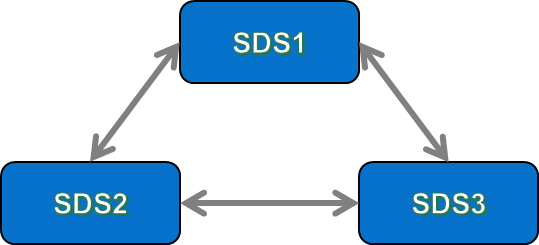
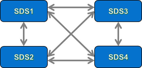
Now, it does not take a genius to see that with a 3-node system, there are 3 data paths between all of the SDSs in the system, but when we added in a 4th SDS, the number of paths increased – in the example above, we went from 3 data paths in a 3-SDS system, to 6 data paths in the 4-SDS system. To keep things simple here, let us not get too deep in “how” those paths are actually configured at the network layer (that is another conversation entirely!). The important thing to point out here is that when we add each new SDS into the system, it creates a new data path between itself & every other SDS in the same Protection Domain. This explains why the both the maximum IOPS performance available & the total aggregate bandwidth of a PowerFlex system increases as new nodes are added into the system.
So, what happens when an SDS fails? Once the PowerFlex MDM detects that an SDS has failed, the rebuild process will automatically kick in. The rebuild process ensures that all data chunks that are now down to a single copy due to the failed node will get rebuilt to become fully protected again. The rebuilds take place between the remaining SDS nodes in the PowerFlex system – the rebuild traffic utilises the same network paths as the data paths between the SDS nodes, but the rebuild traffic might be set to deliver a different QoS than regular SDS data traffic. Figures 3 & 4 below show examples of the resultant loss of data paths & rebuild traffic flows for our 3-node and 4 node examples that were shown earlier:
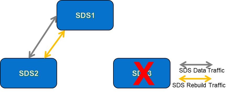
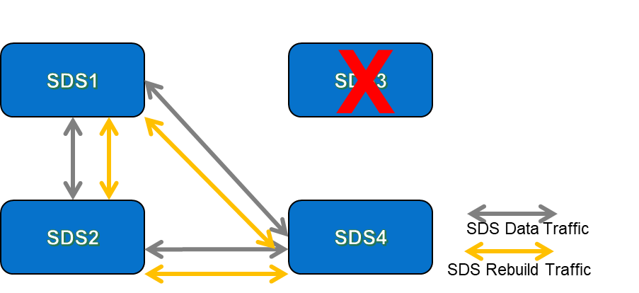
It is obvious that rebuild activities will compete quicker in a 4-node system than it will in a 3-node system because when we have more nodes available, there are more traffic paths available for rebuild traffic to take place on. I am assuming here that the network latency between all nodes is equal – or, to put it another way, that all of the nodes in our examples are connected to the same top-of-rack network switches. Having more SDS nodes means that there is more bandwidth available for storage traffic; not only for “normal” storage data traffic, but also for rebuild/rebalance traffic in the event of something happening at the storage layer that triggers either a rebuild (disk or node failure) or rebalance (addition of a new disk or node).
PowerFlex Rebuild Process – With Fault Sets
Now that we have refreshed our memories as to how the rebuild process works for PowerFlex systems that are not using Fault Sets, let us examine the rebuild process with them added into the mix. As mentioned earlier above, I would refer you to Kevin Jones’ excellent blog for a reminder of what Fault Sets are and why you would use them. We are currently seeing a lot of interest in the use of Fault Sets from customers who are considering deploying Dells’ APEX Block Storage for AWS, which uses PowerFlex running on AWS compute instances. This offers the ability to configure the SDS nodes across Availability Zones that reside in the same Amazon region, in order to provide storage-level availability in the event of an entire AWS Availability Zone outage.
I recently had a conversation with a customer who made a statement along the lines of “using Fault Sets means that I get better rebuild times than if I do not use them, right?”. At first glance, there does appear to be some substance to making such a statement – because to use Fault Sets you would need at least 3 Fault Sets, but you need a minimum of 2 nodes per Fault Set … so, that means I have a minimum of 6 nodes, plus when a node fails, there is less rebuild traffic, right?
The best way to prove such thinking is this – first, we need to explain how rebuilds with Fault Sets work. Having done that, we can then compare that with an example that has the same number of nodes but does not use Fault Sets. At which point, the answer will become apparent!
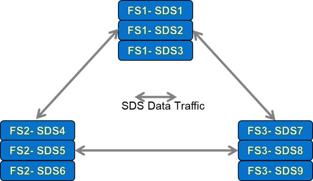
So, I am now going to examine a couple of scenarios to illustrate both configurations, using 9 SDS nodes in each. For the first scenario, the 9 nodes are configured into what I will term as a “3×3” Configuration – a PowerFlex system consisting of Three Fault Sets, each of which has three SDS nodes per Fault Set. It is this scenario that many customers are thinking of using when deploying PowerFlex into the public cloud, with each Fault Set deployed onto different Availability Zones in AWS to obtain the protection against AWS AZ failures.
In the second scenario, the 9 SDS nodes are configured using the system default where each SDS is its own “Fault Set of 1” – indeed, the PowerFlex documentation differentiates between a Fault Set that contains multiple nodes and a Fault Set with single SDS on its own by using the term ‘Fault Unit’, as follows – “When defining Fault Sets, we refer to the term fault units, where a fault unit can be either a Fault Set, or an SDS not associated with a Fault Set (you may think of it as a Fault Set of a single SDS).” There – I am glad that we cleared that one up!
So, let us first look at how the three Fault Set “3×3” configuration looks like during normal BAU operations:
At first glance, it appears that we only have 3 “Data Paths” between the 3 Fault sets. Remember that with Fault Sets, the whole premise is that both copies of a chunk of data must reside in different Fault Sets, so that if one Fault Set fails, then data remains available to applications from one of remaining SDSs that houses the secondary chunk of data.
The upshot of this is that when a write IO is made to a Primary SDS within a system that uses 3 Fault Sets, the secondary write must be made to one of the other SDS’s outside the Fault Set of the primary SDS. As an example of this, for any write IO being written to SDS1, then the secondary write could not be made to SDS2 or SDS3, because those two nodes are in the same Fault Set as SDS1. In total, with 9 SDS Nodes configured into three 3-Node Fault Sets, there would actually be a total of 27 unique data paths. All of the available data paths are detailed in Figure 6 below:
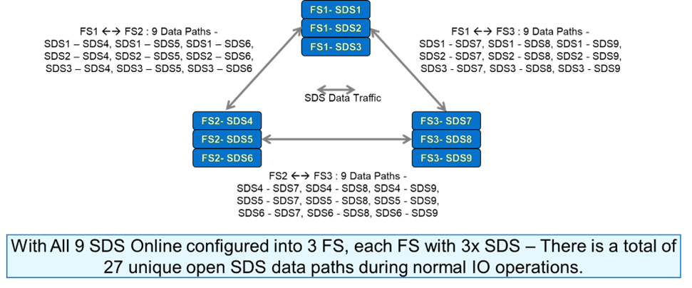
We can see from Figure 6 that when we are using three Fault Sets, there are lots of data paths available for the traffic between the SDS nodes. But what happens if we lose one of the Fault Sets? It stands to reason that we will lose 3 SDS’s worth of data paths, as shown in the figure below:
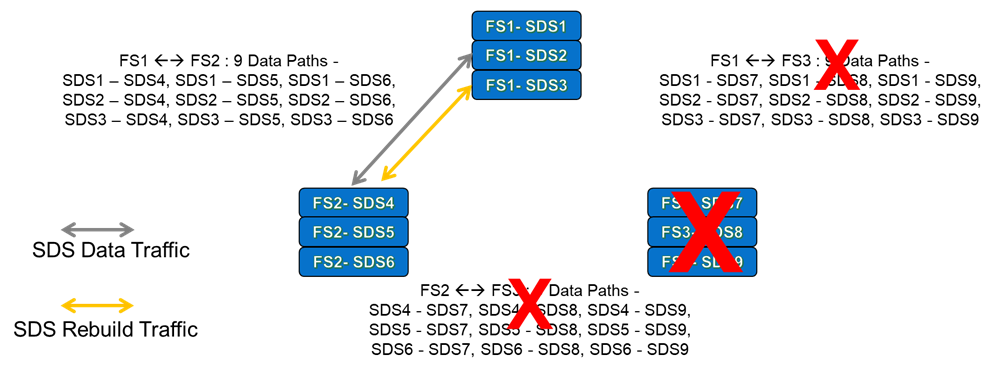
In Figure 7, Fault Set 3 has failed, so we have lost all data paths that involved the SDS nodes in Fault Set 3. We now have a total of 9 available traffic paths – the total of paths available between the SDS nodes in Fault Sets 1 and 2. Or to put it another way – when we have three Fault Sets and one of them has failed, we now have 1/3rd of the storage bandwidth available compared to when all 3 Fault Sets/9 Nodes were working normally (we are again assuming that the network latencies in this scenario are the same across & between all three Fault Sets). However, despite the failed Fault Set, our applications can still access their storage.
The above example highlights why the use of Fault Sets across Availability Zones in AWS (or other public clouds – watch this space!) is attractive for some customers – typically, if all of the storage being used is located in one AZ and is not being replicated to a second AZ, then an AZ failure of the Zone where the storage is located will cause any applications using that storage to crash due to storage unavailability. But with PowerFlex Fault Sets, we can see that even when one third of our SDS (EC2 instances) have failed due to an AZ outage, we still have access to the storage, with the result that application instances running in other AZs still continue to run, regardless of the issues in AZ3 (assuming here that Fault Set 3 was deployed in AZ3).
One other point to make clear here – in the “3×3” configuration, if we only lose a single node in any Fault Set, then any data chunks located on the failed node will need to be re-protected. These rebuilds will happen into the spare capacity available in the SDS nodes resident in the other Fault Sets – so in this scenario, rebuilds only occur across a subset of all of the SDS nodes in the system.
Let us get back to the original statement that we are trying to prove (or disprove!) – that “using Fault Sets means that I get better rebuild times than if I do not use them, right?”… Hopefully, the previous “Fault Set” scenario is starting to underpin your understanding now, but, in the interests of completeness, lets discuss the second scenario, using all 9 SDS nodes, where each SDS is its own ‘Fault Unit’. Figure 8 below highlights the traffic paths from just one of these 9 SDS nodes:
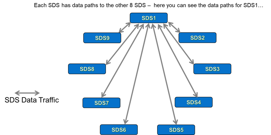
How many traffic paths do we have in total? Well, with 9 SDS, we see a total of 36 unique data paths (8+7+6+5+4+3+2+1). This compares with the 27 data paths that we had when running with 9 Nodes configured across our “3×3” Fault Set configuration. Or to put it another way – we get 33% more data paths for a 9 Node PowerFlex system when they are not configured to use 3 Fault Sets.
With this understanding, the penny should now be dropping as to how accurate the earlier statement was, but once again -in the interests of completeness- let us also check what happens when we lose a single SDS in our 9-Node PowerFlex system.
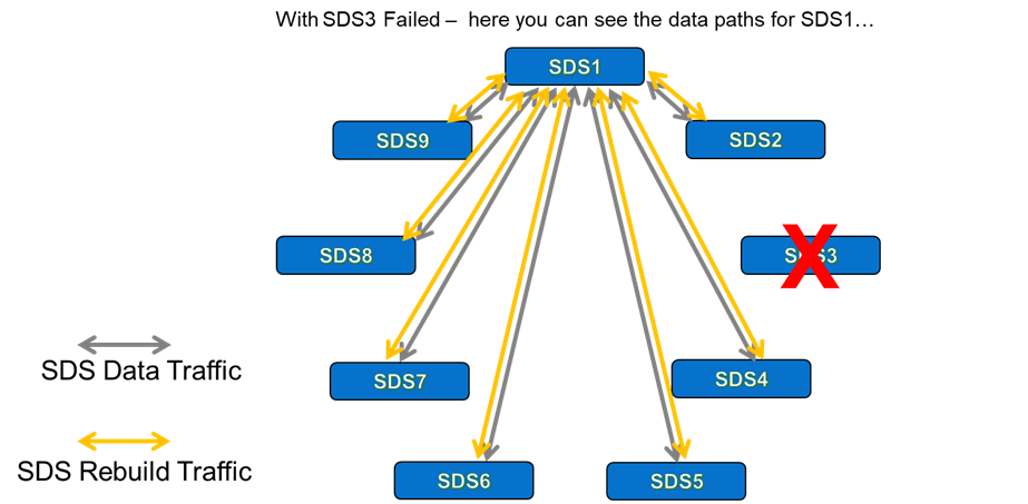
Figure 9 shows the situation with a single failed SDS, SDS3. While we have lost all traffic paths that involved SDS3, we still have 28 unique traffic paths available to us (7+6+5…+2+1). Equally important – we can rebuild across all remaining SDS nodes, not just the ones that exist in the different Fault Sets to the one that we reside in, which was the case for our “3×3” configuration earlier. In the scenario where a single SDS fails, it actually means that we have 3.11 times more bandwidth available to us to perform rebuilds, because we have 8 available SDS nodes to rebuild across, instead of the 6 SDS nodes we had when the “3×3” Fault Set configuration was chosen.
We can see from the second scenario that has all 9 SDS configured “as individual fault units” that this configuration provides more bandwidth than the “3×3” scenario which uses Fault Sets. The head-to-head comparison of scenarios clearly shows that when an SDS fails, we will rebuild & re-protect our data much quicker in a scenario that does not use Fault Sets, simply because we have more storage bandwidth available. This is because when an SDS fails in a configuration that uses Fault Sets, then we are unable to rebuild into the spare capacity of the other SDS nodes that reside in the same Fault Set as the failed SDS – we had two nodes fewer to rebuild into in the example we have discussed above. This is part & parcel of how Fault Sets were designed to work.
However, we can clearly also see that Fault Sets have a role to play when deployed in public clouds, where the hyperscalers are able to provide fat-pipes between AZs that offer network bandwidth numbers that would cost a fortune were you to try & replicate such a setup between your typical “on-prem” datacenters! Ultimately, both deployment options have their own merits and I would expect to see Fault Sets becoming more widely used with future PowerFlex deployments in the cloud.